
Guide · Electrode Materials
Battery Current Collectors: Copper vs Aluminum Foil, Coatings, and Spec Trade-Offs
A battery current collector is the metal foil or conductive substrate that carries electrons between the coated electrode and the tab, but the selection problem is larger than conductivity alone. For most lithium-ion cells, copper belongs on the anode side and aluminum on the cathode side. After that first decision, thickness, roughness, coatings, edge quality, and handling strength determine whether the electrode survives coating, calendering, slitting, winding, and formation without creating hidden yield loss.
That matters to Xnergy customers because current collectors are often purchased too late in the development flow. Teams may tune active material, binder, and electrolyte first, then discover that the foil tears during handling, the cathode loses adhesion after drying, or a thinner collector saved mass on paper but narrowed the process window in reality. A better workflow chooses the collector and the validation plan together.
This article stays at that engineering-and-procurement layer. It does not replace Xnergy product pages for high-purity copper foil, battery-grade aluminum foil, or carbon-coated aluminum foil. Instead, it explains how to decide which collector type belongs in the build, what specification matters most, and what incoming-QC or line trial should prove the choice before you commit to prototype or pilot lots.
What a battery current collector actually has to do
A current collector is not just a thin piece of metal. Reviews of lithium-ion current collectors describe it as the conductive backbone that collects charge, supports the electrode coating, influences interfacial resistance, and helps the electrode survive manufacturing and cycling stresses. In practice, that means one material decision affects electrochemistry, coatability, slitting yield, winding behavior, tab joining, and even how the cell responds under abuse or corrosion conditions. See the collector review archived by the University of Birmingham and the corresponding ScienceDirect article landing page for a fuller research view.
The easiest way to under-spec a collector is to treat it as inactive mass that should always be made thinner. Lower inactive mass can help energy density, but only if the foil still stays flat, survives web tension, accepts the coating evenly, and holds together after calendering and cell assembly. If the process window collapses, the theoretical density gain often disappears into scrap, rework, or unstable quality.
That is why the collector decision belongs beside the rest of the electrode build. If you are also choosing binders, conductive additives, and coated-sheet supply, start with Xnergy’s broader electrode essentials guide. If the program is already sourcing complete material sets, the battery research materials buyer’s guide is the right companion page. This post narrows in on the collector itself.
Copper vs aluminum foil: which side, and why?
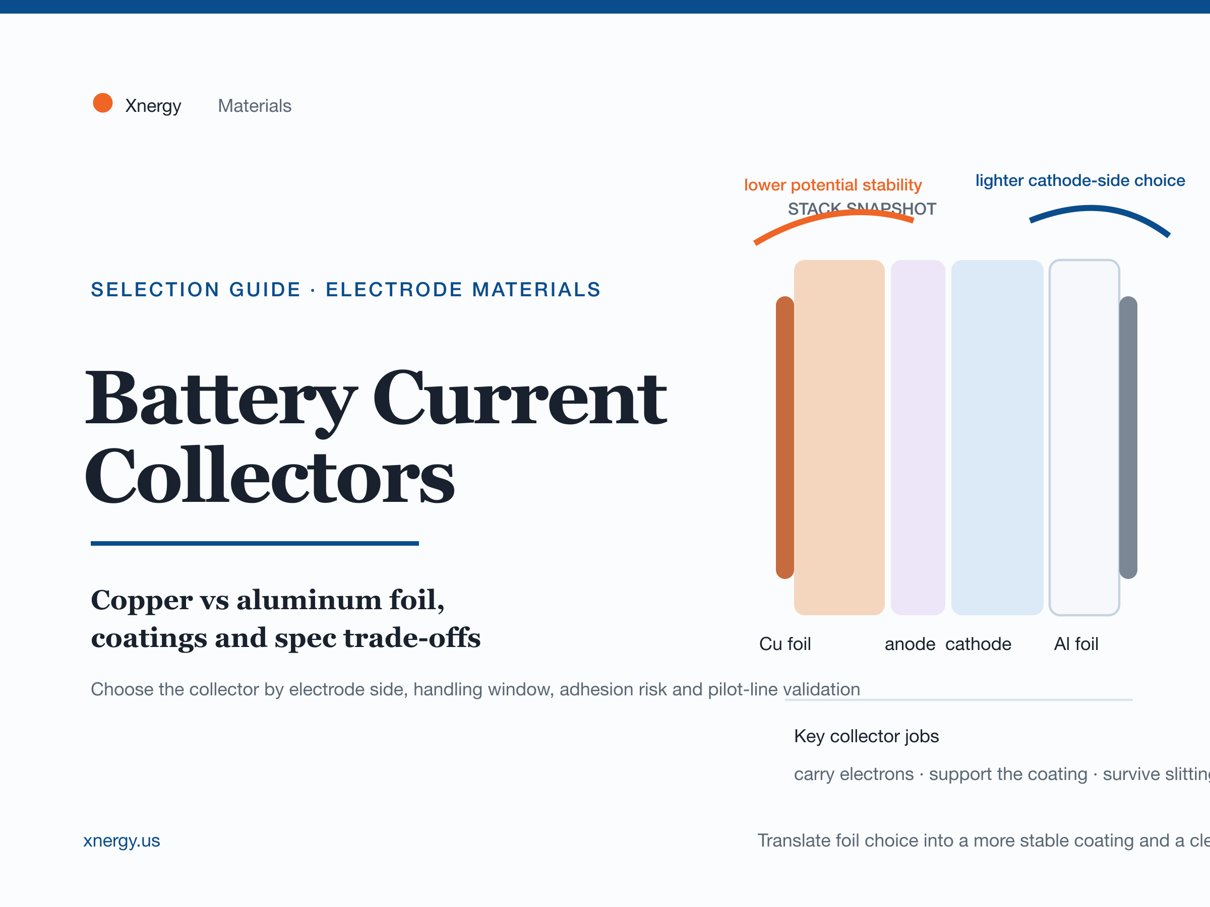
For conventional lithium-ion cells, the rule is simple: copper is typically used as the anode current collector and aluminum as the cathode current collector. Samsung SDI’s battery explainer summarizes the practical logic well: copper is preferred on the anode side because it remains suitable in the low-potential environment there, while aluminum is favored on the cathode side because it is lighter and appropriate for the positive electrode environment. That rule of thumb is the correct default for most graphite-based anodes and mainstream cathode chemistries such as LFP, NCM, NCA, and LCO. The Samsung overview is a useful non-academic reference for that split: Why Aluminum for the Cathode and Copper for the Anode?
Once the electrode side is fixed, the practical question becomes which foil spec. Xnergy’s current copper foil range documents thickness options from 4.5 to 25 μm for anode builds, while the battery-grade aluminum foil range documents 9 to 20 μm for cathodes. That thickness window alone tells you the problem is not purely electrochemical. Thinner foil reduces inactive mass; thicker foil usually buys mechanical margin, flatter handling, or more forgiving line behavior. What matters is the foil that preserves the process window your build actually needs.
For teams working with standard cathode sheets or custom-coated electrodes, current collector selection should stay linked to the final coated-electrode target. If the downstream decision is still open, Xnergy’s lithium-ion cathode sheets guide and sodium-ion cathode sheets guide help frame the rest of the electrode specification. The collector should not be chosen in isolation from loading, density, or cell format.
How to specify thickness, roughness, coatings, and handling margin
The most useful way to buy current collectors is to translate the cell design into a short specification brief. That brief should answer five questions before the first quote goes out.
- Which electrode side and chemistry? This decides the default metal choice first.
- What loading and energy-density target matter? This sets the pressure to go thinner or stay conservative.
- What manufacturing steps will the collector see? Coating, drying, calendering, slitting, winding, stacking, and tab joining all matter.
- What failure is most expensive? Tearing, burrs, weak adhesion, high resistance, corrosion, or unstable storage behavior do not carry the same cost.
- What test will accept or reject the lot? Incoming QC must be defined before the material shows up.
Those questions usually narrow the foil spec faster than a generic request for the “best” current collector. For example, an anode program trying to lower inactive mass may move toward thinner copper foil, but only if the web remains stable through coating and slitting. A cathode team targeting heavier loading may stay with a more robust aluminum foil or test carbon-coated aluminum if adhesion or contact resistance becomes the bottleneck. The key is to buy a collector for the line and the electrode, not only for the data sheet.
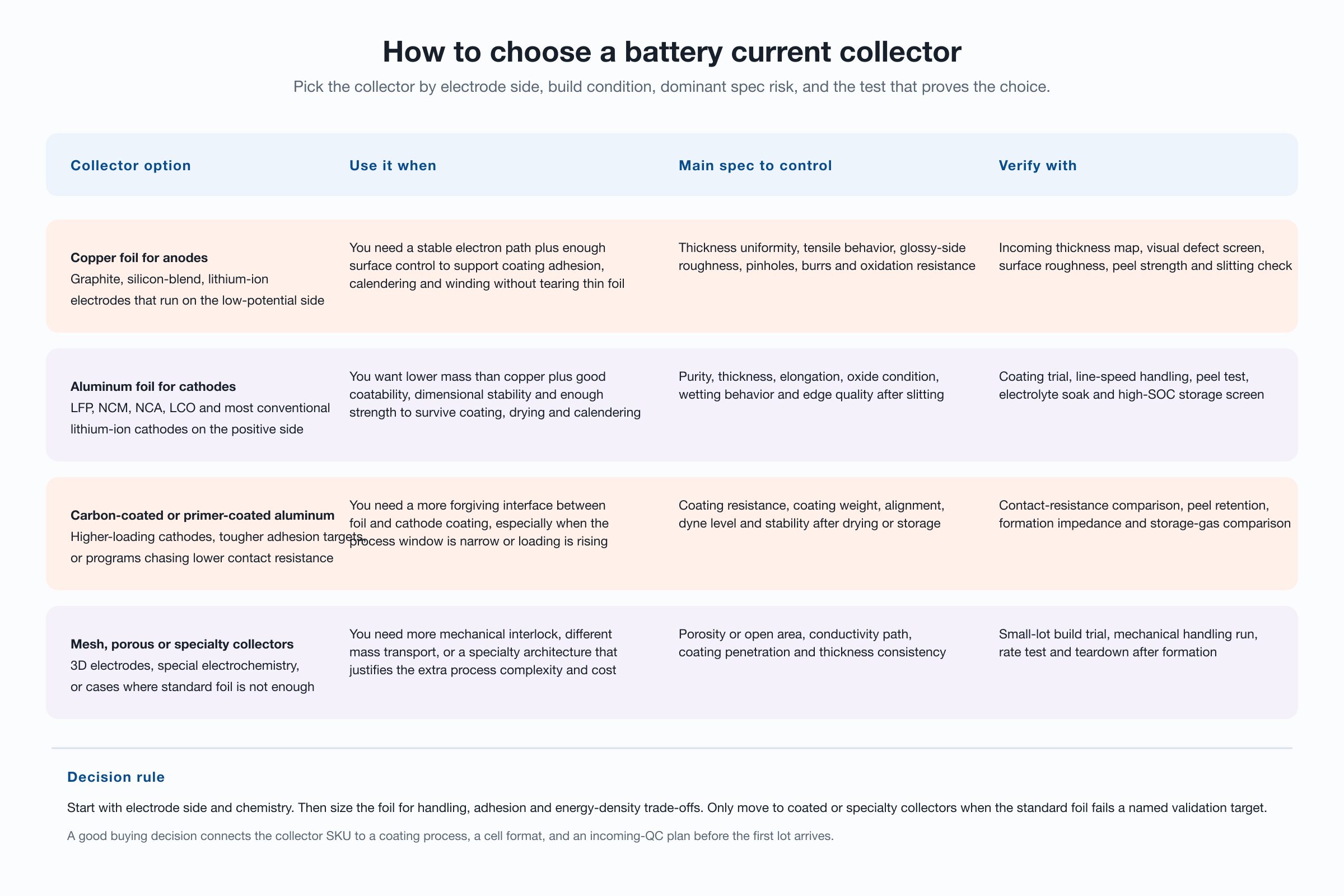
| Collector format | Best-fit use case | Main spec focus | Common failure risk | Validate first |
|---|---|---|---|---|
| Copper foil | Graphite or silicon-blend anodes in conventional Li-ion cells | Thickness uniformity, roughness, tensile behavior, oxidation resistance | Tearing, edge damage, weak adhesion after coating | Thickness map, defect screen, peel and slitting trial |
| Aluminum foil | Mainstream cathodes such as LFP, NCM, NCA, and LCO | Purity, thickness, elongation, wetting and edge quality | Adhesion loss, line instability, corrosion or storage drift | Coating trial, peel test, soak or storage screen |
| Carbon-coated aluminum | Cathodes needing lower contact resistance or more forgiving adhesion | Coating resistance, coat weight, alignment, surface energy | Inconsistent coated layer or weak line-to-line repeatability | Contact-resistance comparison and formation-EIS check |
| Mesh or porous collectors | Special architectures, 3D structures, or niche electrochemistry work | Open area, conductivity path, mechanical interlock | Higher cost and more difficult coating or handling | Small-lot build test and teardown after formation |
Edge quality deserves extra attention because it is one of the easiest ways for a good foil to become a bad electrode later. A foil can meet nominal thickness, then lose value if the slitting result creates burrs, edge cracking, or unstable tab areas. Roughness matters for similar reasons. Too little surface character may not support coating adhesion well enough; too much may narrow the process window or complicate thickness control. The right answer is not universal. It depends on the coating system and the line.
When coated, mesh, or specialty current collectors are worth testing
Specialty collectors make sense when bare foil fails a named job. The most common step beyond standard aluminum is a coated foil, especially carbon-coated aluminum for cathodes. The point is not decoration. A coated layer can improve contact behavior, support adhesion, or widen the manufacturing window when higher loading or tougher process conditions make bare foil less forgiving. Xnergy’s water-based carbon-coated aluminum foil is relevant for exactly that kind of program because it offers single- and double-sided configurations instead of forcing one default.
That said, coated foil should still be treated as a hypothesis to validate, not as a premium upgrade you buy automatically. The questions are concrete. Does it lower contact resistance enough to matter? Does peel strength improve after drying and calendering? Does the coated interface hold up after storage or formation? If the answer is no, the extra cost and complexity may not be justified.
Mesh, porous, or other specialty collectors belong in an even narrower set of cases. They can help when a program needs mechanical interlock, unusual mass transport, or a structured current path that standard foil cannot provide. Review literature treats these architectures as real opportunities, but also as process complications that require proof. Unless the cell architecture truly needs them, standard foil remains the safer default for most lithium-ion electrode lines.
Qualification workflow before you lock the BOM
The best collector programs use a short incoming-QC and line-trial workflow before the material becomes part of a repeat build. Oak Ridge National Laboratory and the Faraday Institution have both highlighted how collector corrosion and failure behavior can become serious problems under abuse or off-normal conditions. You do not need to run a full failure-analysis campaign for every lot, but you do need a qualification plan that catches the obvious mismatches early. Their poster on collector corrosion and failure behavior is a useful reminder that collector choice affects more than nominal conductivity: Current Collectors: Corrosion, Behaviour and Decomposition During Cell Failure.
- Define the collector brief. Electrode side, chemistry, target loading, cell format, and the handling steps it must survive.
- Run incoming checks. Confirm thickness, width, visible defects, roughness, and any coated-layer requirement such as resistance or coat weight.
- Build a coating trial. Watch web stability, slurry wetting, adhesion, and edge condition after drying and calendering.
- Stress the likely failure point. For anodes, that may be thin-foil handling or slitting; for cathodes, it may be adhesion, storage, or corrosion risk.
- Promote only proven material. Once the foil survives the line trial, move it into prototype cells or pilot lots with the rest of the locked bill of materials.
This is where Xnergy’s one-stop model is most useful. Many buyers do not need a foil vendor alone. They need the foil plus compatible powder, binder, additive, coated-electrode support, or prototype-cell execution. If the collector choice is entangled with the rest of the electrode build, it is usually more efficient to qualify the package together instead of solving each material in a separate vendor loop.
Collector selection support
Need foil samples or a coordinated electrode package?
Send Xnergy your chemistry, target loading, cell format, foil preference, and the failure mode you need to avoid. We can support copper foil, aluminum foil, coated collectors, custom electrodes, prototype cells, and pilot-manufacturing handoff from one US-based battery materials partner.
Frequently asked questions
What is a battery current collector?
A battery current collector is the conductive foil or substrate that carries electrons into and out of the coated electrode while also supporting coating, calendering, slitting, tabbing, and cell assembly.
Why is copper used for the anode and aluminum for the cathode?
In conventional lithium-ion cells, copper is the usual anode current collector because it is stable on the low-potential side, while aluminum is usually chosen for the cathode because it is lighter and suitable on the positive side.
How thin should current collector foil be?
The right thickness depends on the electrode loading, cell format, handling stress, and energy-density target. Thinner foil can reduce inactive mass, but only if it still survives coating, drying, calendering, slitting, and winding without damage.
When is carbon-coated aluminum foil worth it?
Carbon-coated aluminum foil is worth testing when a cathode needs better contact resistance, more stable adhesion, or a wider process window than bare aluminum can provide.
What should incoming QC check before coating starts?
Incoming QC should check thickness, width, edge quality, visible defects, roughness, mechanical handling performance, and any coated-layer requirements such as coat weight, alignment, and resistance.
Can mesh or porous current collectors replace standard foil?
Sometimes, but only when the cell architecture needs the added surface structure or mechanical interlock enough to justify the higher cost and process complexity. Standard foil remains the default for most lithium-ion electrode builds.