
Guide · Cell Materials
Lithium-Ion Battery Components: What Each Part Does and How to Specify It
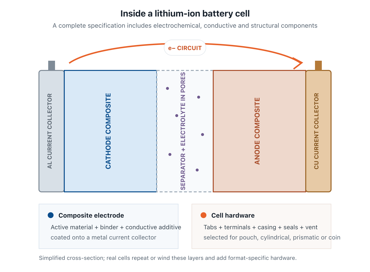
The four core battery components are the positive electrode, negative electrode, electrolyte and separator. A buildable lithium-ion cell also needs current collectors, binders, conductive additives, tabs or terminals, a casing and reliable seals. Each part has a different job, but none works independently.
That distinction matters when a research result becomes a cell specification. Selecting a high-capacity cathode is not enough if the electrolyte oxidizes at its upper voltage, the separator wets poorly, the binder loses adhesion or the anode loading leaves too little capacity margin. This guide maps the complete component stack and shows what to specify before ordering materials or building prototypes.
The lithium-ion battery component map
The common “four-component” description is electrochemically useful: two electrodes store lithium, the electrolyte transports ions and the separator prevents electronic contact. Manufacturing adds another layer of detail. Each electrode is a composite coating attached to metal foil; the foils connect through tabs and terminals; the assembly is contained by pouch film or a metal can.
| Component | Primary job | Specification examples |
|---|---|---|
| Cathode composite | Stores lithium at higher potential; strongly influences voltage, energy and cost | Chemistry, capacity, particle size, coating, loading, density |
| Anode composite | Stores lithium at lower potential; influences charge acceptance and first-cycle loss | Material, efficiency, expansion, loading, porosity, surface area |
| Electrolyte | Conducts ions and creates functional electrode interfaces | Salt, solvent, additives, concentration, water, voltage/temperature window |
| Separator | Prevents electrode contact while allowing ionic transport | Material, thickness, porosity, wettability, puncture and thermal behavior |
| Binder | Provides particle cohesion and collector adhesion | Polymer, solvent system, solids fraction, adhesion, elasticity |
| Conductive additive | Builds electronic pathways through the coating | Carbon type, morphology, surface area, dispersion, loading |
| Current collectors | Carry electrons and support electrode coatings | Metal, thickness, treatment, roughness, cleanliness, tab geometry |
| Hardware | Contains, connects and protects the cell | Format, casing, seal, terminal, vent, gasket and pressure design |
The U.S. Department of Energy’s lithium-ion technology assessment describes the same system: active materials on current collectors, an ion-conducting electrolyte and a separator that prevents the electrodes from touching or shorting. The design details determine whether those parts operate as a cell rather than a list of materials.
Cathode and anode: more than active-material powder
A conventional lithium-ion electrode contains active material, binder and conductive additive coated onto a current collector. The active material provides most of the reversible capacity. The other ingredients make that capacity electronically accessible and mechanically manufacturable.
Cathode composite
Common cathode active materials include lithium iron phosphate (LFP), lithium nickel manganese cobalt oxide (NMC), lithium nickel cobalt aluminum oxide (NCA), lithium cobalt oxide (LCO) and related families. Chemistry establishes the broad voltage and capacity range, but particle morphology, residual impurities, surface treatment, carbon coating and electrode density can decide practical performance. The cathode materials guide covers these choices in depth.
Anode composite
Graphite is the established lithium-ion anode. Silicon-graphite can raise capacity but adds expansion and interphase challenges; lithium titanate (LTO) trades cell voltage for rate and lifetime advantages; lithium metal changes the architecture more radically. For silicon-specific formulation and validation issues, see the silicon anode guide.
The full cell must balance usable positive- and negative-electrode capacity, including first-cycle loss and manufacturing tolerance. A half-cell result does not establish the final negative-to-positive capacity ratio, voltage window or lithium inventory. Our cathode vs anode guide explains that pairing logic.
Electrolyte and separator form the ion pathway
Electrons should travel through the external circuit; ions must travel inside the cell. The electrolyte and separator create that internal pathway.
Electrolyte
A conventional liquid lithium-ion electrolyte combines a lithium salt with organic solvents and functional additives. It fills the pores of both electrodes and the separator. Conductivity is only one requirement: the formulation also has to wet the porous stack, remain sufficiently stable across both electrode potentials and form protective interphases during formation.
Salt concentration, solvent ratio, additive package, water content and impurity control all matter. A formula that performs well with graphite/LFP may not be the right starting point for silicon/high-nickel NMC or lithium metal. Compare liquid, gel and solid approaches in the battery electrolyte selection guide.
Separator
The separator is a thin, electrically insulating membrane between the electrodes. Its electrolyte-filled pores permit ion transport while preventing direct electronic contact. Conventional separators may use polyethylene (PE), polypropylene (PP), multilayer films or ceramic-coated polymer structures.
Thickness, porosity, pore structure, wettability, tensile and puncture strength, thermal shrinkage and shutdown behavior affect resistance, assembly yield and safety. A lower-resistance separator is not automatically better if it loses mechanical integrity or thermal dimensional stability in the intended process.
In many all-solid-state designs, the solid electrolyte also supplies physical separation, so the component boundary changes. Argonne National Laboratory’s comparison of conventional and solid-state cells notes that the production process and component arrangement can differ substantially even when the underlying ion-transfer principle remains familiar.
Binders and conductive additives make electrodes work
Active-material particles alone rarely form a robust, conductive coating. The binder and conductive additive create two different networks.
- Binder network: holds particles together, adheres the coating to the foil and accommodates mechanical stress during drying, calendering and cycling.
- Electronic network: conductive carbon or another additive connects active particles to each other and to the current collector.
Polyvinylidene fluoride (PVDF) with N-methyl-2-pyrrolidone (NMP) is common in cathode processing. Water-based carboxymethyl cellulose/styrene-butadiene rubber (CMC/SBR) systems are common for graphite anodes. PTFE can support dry-electrode approaches. These are patterns, not interchangeable defaults: active-material surface chemistry, slurry pH, solvent compatibility, elasticity and drying conditions all affect the correct system.
An OSTI-hosted electrode-processing study summarizes the roles clearly: conductive additives improve electronic conduction, while binder provides both cohesion within the coating and adhesion to the collector. Both occupy mass and volume without supplying the main reversible capacity, so the goal is an efficient network, not the highest possible loading.
The electrode essentials guide goes deeper into formulation and the powder-to-electrode process.
Current collectors, tabs and terminals carry electrons
Current collectors provide a continuous electronic path and mechanical support for electrode coatings. Conventional lithium-ion cathodes generally use aluminum foil; conventional graphite anodes use copper foil. This choice follows electrochemical stability as well as conductivity and mass. LTO is a notable exception that may use aluminum on the negative side because of its higher operating potential.
A working foil specification includes more than metal type:
- thickness and areal mass;
- surface roughness, treatment or carbon coating;
- tensile behavior and edge quality;
- cleanliness, oxide condition and corrosion compatibility;
- coating adhesion and uncoated tab geometry.
Tabs connect the collector foils to the external terminals. Material, thickness, weld method, current density and seal compatibility matter. A highly conductive electrode stack can still fail through an inconsistent weld, overheated tab or corroding terminal interface.
Casing, seals and safety hardware depend on cell format
Pouch, cylindrical, prismatic and coin cells package similar electrochemical layers differently. A pouch uses a laminated barrier film and heat-sealed tab regions. Cylindrical and prismatic cells use metal cans, insulated feedthroughs and format-specific closure systems. Coin cells use cases, spacers, springs and gaskets to maintain contact and sealing.
Depending on format, the design may add a vent, current-interrupt device, positive-temperature-coefficient element or other safety hardware. These are not decorative packaging details. The enclosure manages moisture ingress, electrolyte loss, internal pressure, electrical isolation and mechanical constraint. Stack pressure can be especially important for silicon-rich, lithium-metal and solid-state designs.
At this boundary it helps to separate cell scope from pack scope. Busbars, battery-management electronics, thermal plates and pack housings are essential at module or pack level, but they are not part of the internal cell material stack addressed here.
Develop with Xnergy
Turn a component list into a compatible cell
Send us your chemistry, voltage and capacity targets, C-rate, temperature window, cell format, electrode loading and validation stage. Xnergy can coordinate materials, custom electrodes, cell prototypes and pilot validation around one working specification.
Battery components must be specified as interfaces
Most costly cell-development problems occur at interfaces rather than inside an isolated datasheet. Use these compatibility checks before committing to a bill of materials:
- Electrode/electrolyte: confirm the positive and negative operating potentials fit the electrolyte and additive strategy.
- Electrode capacity: balance measured usable capacity, first-cycle efficiency, loading tolerance and aging margin.
- Slurry/collector: verify solvent, pH, surface treatment, coating adhesion and corrosion behavior.
- Electrolyte/separator: measure wetting, uptake and resistance with the actual formulation rather than relying on a generic separator value.
- Electrode/separator: check particle defects, burrs, alignment, compression and puncture risk in the intended assembly process.
- Stack/hardware: account for swelling, gas, stack pressure, tab current and enclosure tolerance across temperature and aging.
A component can pass incoming inspection and still fail in combination. DOE’s Battery Data Hub reflects this systems view by recording electrode loading, porosity, binders, conductive additives, current collectors, separator, electrolyte, N/P ratio and formation information in the same cell dataset.
From datasheets to a complete cell specification
Before requesting samples or prototype work, document these inputs:
- chemistry and target voltage window;
- cell format, nominal capacity and dimensional limits;
- charge/discharge rate and pulse requirements;
- operating and storage temperature;
- cathode and anode loading, density, thickness and porosity;
- measured first-cycle efficiency and capacity balance;
- electrolyte formulation, fill amount and moisture limit;
- separator material, thickness and coating;
- collector thickness, surface treatment and tab design;
- formation protocol, rest steps and acceptance criteria;
- cycle-life, impedance, gas, swelling and safety test plan;
- lot traceability, sample quantity and scale-up requirement.
Formation is not a purchased component, but it belongs in the specification. Initial charge conditions create the solid-electrolyte interphase and condition the cathode interface; current, temperature, pressure and rest time can change irreversible loss, gas and impedance. A cell built from identical materials can perform differently under a different formation protocol.
Start with the simplest cell format that answers the research question, then repeat critical results in the intended architecture. Coin cells are efficient for screening, but pouch or cylindrical prototypes expose electrode area, wetting, pressure, tab, gas and thermal effects that small cells can hide. The battery research materials buyer’s guide provides a deeper sourcing path by chemistry.
Frequently asked questions
What are the main components of a lithium-ion battery?
The four core components are the positive electrode, negative electrode, electrolyte and separator. A buildable cell also needs current collectors, binders, conductive additives, tabs or terminals, casing and seals. Some formats add vents, gaskets and safety hardware.
Which battery components store energy?
The cathode and anode active materials provide the main reversible lithium storage. The other components enable ion transport, electron transport, mechanical integrity and containment. They may be “inactive” in capacity calculations but are essential to working performance.
What is a lithium-ion electrode made of?
A conventional composite electrode contains active material, polymer binder and conductive additive coated onto metal foil. Cathodes commonly use aluminum foil; graphite-based anodes commonly use copper. Exact formulations vary with chemistry.
What does the separator do?
It prevents direct contact between the positive and negative electrodes while electrolyte-filled pores permit lithium-ion transport. Thickness, porosity, wettability, thermal behavior and puncture resistance influence resistance and safety.
Why are binders and conductive additives needed?
Binder provides cohesion and collector adhesion. Conductive additive creates electronic pathways through the coating. Both add inactive mass, so the correct type, dispersion and minimum effective amount matter.
Can battery components be selected independently?
No. Electrode potentials must fit the electrolyte; separator wetting must fit the formulation; binder must fit the powder and process; and capacity, porosity and hardware must fit the rate and format. Validate the complete cell.