
Guide · Cell Design
Fast-Charging Batteries: Material Limits, Lithium Plating, and Design Trade-Offs
A fast-charging battery is not simply a normal cell connected to a higher-power charger. The cell must move lithium ions through its electrolyte and porous electrodes, transfer them across interfaces, store them inside active materials and dissipate the resulting heat—without plating metallic lithium or accelerating destructive side reactions.
The practical target is therefore not the highest possible current. It is the shortest charge time that stays inside a validated electrochemical and thermal envelope across temperature, state of charge, aging and manufacturing variation. Materials, electrode architecture, cell hardware and charging controls all set that envelope.
What makes a battery fast-charging?
A fast-chargeable cell has low enough resistance and fast enough transport at every step in the charge path. Lithium ions have to travel through the electrolyte-filled separator and electrode pores, shed part of their solvation shell at the anode interface, cross the solid-electrolyte interphase (SEI) and diffuse into the anode particles. Electrons arrive through tabs, current collectors and a conductive electrode network at the same time.
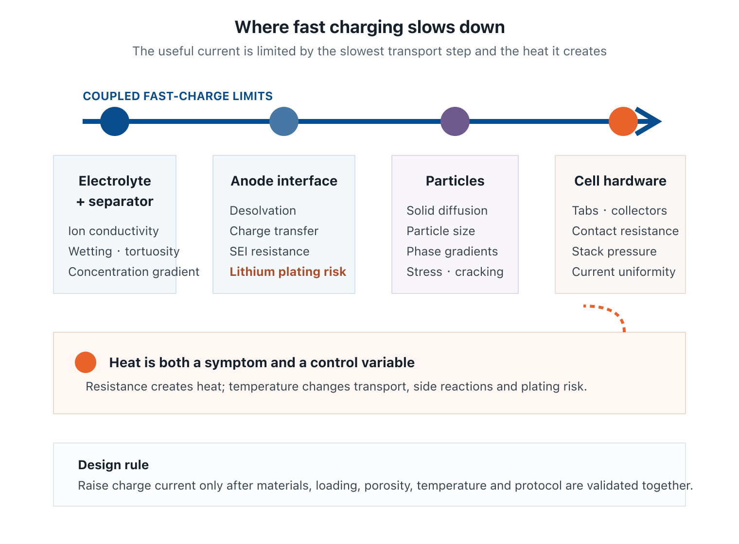
If any step becomes slower than the applied current demands, concentration and potential gradients grow. Those gradients create polarization, uneven reaction, heat and, at the graphite anode, possible lithium plating. A powerful charger can supply current; it cannot remove these internal limits.
This systems view follows the U.S. Department of Energy’s extreme fast-charging program, which treats anode material, cell design, electrolyte optimization, plating detection and complete-cell testing as one development problem.
C-rate, charge time and the CC-CV reality
C-rate normalizes current by nominal cell capacity. For a 5 Ah cell:
- 0.5C is 2.5 A;
- 1C is 5 A;
- 2C is 10 A;
- 4C is 20 A.
In an ideal constant-current calculation, 1C corresponds to one hour and 4C to 15 minutes. That does not mean a real lithium-ion cell reaches a true full charge in exactly those times. Capacity is rate- and temperature-dependent, and most lithium-ion cells use constant-current/constant-voltage (CC-CV) charging.
During the constant-current stage, voltage rises while the charger holds the programmed current. When the cell reaches its upper voltage limit, the charger holds that voltage and current tapers. The last portion of charge therefore takes progressively longer. A credible fast-charge claim must specify the starting and ending state of charge, temperature, maximum voltage, current profile and end-of-charge condition.
Where fast charging slows down inside the cell
Electrolyte and porous-electrode transport
High current can deplete lithium-ion concentration locally and increase concentration gradients through thick electrodes. Ionic conductivity, electrolyte viscosity, salt concentration, separator resistance, wetting, electrode porosity and tortuosity all influence how uniformly ions reach the reactive surface.
Interfacial charge transfer
At the anode, solvated lithium ions must desolvate, cross the SEI and enter the active material. Interphase chemistry that is stable at low rate may become too resistive or non-uniform under aggressive charging. Aging usually adds further resistance, which is why a fresh-cell fast-charge result does not establish end-of-life capability.
Solid-state diffusion and phase change
Lithium must diffuse inside graphite and cathode particles. Argonne’s operando fast-charge study observed stronger phase gradients across graphite-electrode thickness as charge rate increased. Non-uniform lithiation means some regions approach their limit while other material remains underused.
Electronic resistance and heat
Tabs, welds, collectors, conductive additives and contact resistance create ohmic loss. The resulting heat is not uniform: tab placement, electrode dimensions, cooling boundaries and local wetting can create hot and cold regions. Temperature can improve kinetics up to a point, but it also accelerates side reactions and aging. Thermal uniformity matters as much as an average temperature reading.
Why lithium plating is the central fast-charge risk
Graphite normally stores lithium by intercalating ions between carbon layers. During fast charging, lithium can arrive at the anode surface faster than it can cross the interface and diffuse into graphite. If polarization drives the local anode potential sufficiently low relative to Li/Li+, metallic lithium deposits on the surface instead.
Plating risk rises with:
- high charging current;
- low cell temperature;
- high state of charge;
- thick or high-loading electrodes;
- low porosity, poor wetting or high tortuosity;
- electrode misalignment, edge effects or current non-uniformity;
- increased impedance as the cell ages.
Some freshly plated lithium may later re-intercalate. Some can react with electrolyte or become electronically isolated as inactive lithium, consuming cyclable lithium and raising resistance. Idaho National Laboratory’s battery safety diagnostics work emphasizes both the performance loss and safety implications of plating under extreme fast-charge conditions.
Not all fast-charge degradation is plating. SEI growth, electrolyte decomposition, gas, binder damage, collector-interface loss and cathode cracking can occur at the same time. That is why capacity fade alone cannot identify the root cause.
Anode and cathode choices for fast charging
Graphite anode
Graphite remains attractive because it is mature, efficient and energy-dense, but its low operating potential leaves limited margin before lithium deposition. Particle size, morphology, orientation, surface area, coating, binder system, loading, density and porosity all affect charge acceptance. Smaller particles can shorten solid-diffusion distance but may increase surface area, side reactions and first-cycle loss.
Silicon-graphite and advanced anodes
Adding silicon can increase capacity, but expansion, repeated interphase growth and swelling complicate fast-charge design. A higher-capacity anode does not automatically accept lithium faster. The silicon anode guide explains why particle architecture, binder elasticity, prelithiation and formation need to be treated together.
Lithium titanate (LTO) operates at a higher potential than graphite, reducing the tendency for lithium plating and supporting high-rate operation. The trade-off is lower full-cell voltage and therefore lower energy density. This illustrates a recurring rule: improving rate often costs energy, inactive mass, surface stability or manufacturing simplicity.
Cathode limitations
The anode receives most fast-charge attention, but the cathode also experiences concentration gradients, diffusion-induced stress and particle cracking. High-nickel layered oxides, LFP and other materials have different kinetics and structural responses. Conductive coating, particle architecture, electrode density and upper voltage all influence the result.
Fast-charge performance comes from a matched electrode pair, not a single “fast” material. See the cathode vs anode guide for full-cell capacity and voltage pairing.
Electrolyte, separator and interphase design
The electrolyte must move ions quickly through the bulk and also create interfaces that remain conductive and stable. Useful screening variables include ionic conductivity, viscosity, lithium-ion transference behavior, desolvation energy, salt concentration, additive package, temperature range and compatibility with both electrode potentials.
DOE’s XFC electrolyte program combines modeling and cell testing to reduce interfacial impedance and polarization. This is the right level of evaluation: conductivity measured in a vial is not enough if the formulation creates a resistive SEI, oxidizes at the cathode or wets the separator poorly.
The separator adds ionic resistance and controls wetting, but it also provides mechanical isolation and thermal behavior. Reducing thickness may lower resistance while reducing puncture margin. Higher porosity can improve electrolyte access while changing strength and shrinkage. Selection must balance transport, manufacturing and safety. The battery electrolyte guide covers formulation and sourcing inputs.
Electrode architecture and cell hardware
Fast charge exposes design features that low-loading coin cells can hide:
- Areal loading and thickness: thicker electrodes improve energy per unit inactive material but lengthen ion-transport paths.
- Porosity and tortuosity: insufficient pore access creates gradients; excessive porosity reduces volumetric energy and particle contact.
- Calendering: changes density, adhesion, pore structure and electronic contact simultaneously.
- Electrode alignment and overhang: edge non-uniformity can cause local current concentration and plating.
- Tabs and collectors: geometry and weld resistance control current and temperature distribution.
- Stack pressure: affects contact, porosity, swelling and reaction uniformity.
An Argonne study of conformal pressure during fast charge found coupled effects among pressure, lithium plating, cathode damage and reaction uniformity in the tested pouch-cell system. The lesson is not a universal pressure value; it is that mechanical boundary conditions belong in electrochemical validation.
Use the lithium-ion battery components guide to turn these variables into a complete cell bill of materials and specification.
Develop with Xnergy
Design a cell around the target charge window
Send us the starting and ending SOC, target charge time, temperature range, chemistry, capacity, cell format, electrode loading and cycle-life goal. Xnergy can coordinate materials, custom electrodes, prototypes and a fast-charge validation plan.
The charging protocol is part of the cell design
A cell should not be assigned one maximum charge current for every condition. Charge acceptance changes with temperature, state of charge and age. A practical protocol may use high current where the cell has kinetic margin, then reduce current as state of charge and voltage rise. Controls can also respond to temperature, resistance or model-estimated internal states.
| Design lever | Fast-charge benefit | Trade-off to validate |
|---|---|---|
| Thinner electrode | Shorter ion-transport path | More collector/separator mass per unit energy |
| Higher porosity | Better electrolyte transport | Lower volumetric energy and possible contact loss |
| Smaller particles | Shorter solid-diffusion path | More surface reactions and first-cycle loss |
| LTO anode | High rate with lower plating tendency | Lower full-cell voltage and energy density |
| Warmer charging | Faster kinetics and lower plating risk | More side reactions and thermal-aging exposure |
| Aggressive current | Shorter constant-current stage | More polarization, heat and degradation risk |
Low temperature deserves its own limit because electrolyte transport and interfacial kinetics slow while plating risk rises. The cold-weather lithium battery guide covers preheating, electrolyte and low-temperature charge strategy. Energy targets also constrain rate design; compare the competing mass and loading choices in the high-energy-density battery guide.
How to validate a fast-charging battery
Define the claim before testing. “Fast charge” should include starting and ending SOC, time, temperature, initial and aged condition, voltage limit and capacity-retention target. Then validate in stages:
- Characterize components. Measure electrode loading, thickness, density, porosity, capacity and first-cycle efficiency; verify electrolyte and separator properties.
- Screen rate and temperature. Map charge acceptance across SOC and temperature rather than testing a single room-temperature current.
- Look for plating. Combine electrochemical signals with suitable reference-electrode, relaxation, incremental-capacity, thermal, imaging or post-mortem methods.
- Track more than capacity. Record coulombic efficiency, impedance, heat, gas or swelling, voltage relaxation and current taper.
- Age under the real protocol. Repeat the intended fast-charge frequency, discharge duty, rest periods and temperature history.
- Move to the intended format. Pouch or cylindrical prototypes reveal area, tab, wetting, pressure and thermal gradients that coin cells cannot reproduce.
- Test variation and abuse. Include material lots, process tolerances, aged cells and relevant safety tests before setting operating limits.
There is no universal safe fast-charge C-rate. A rate validated for one graphite/NMC pouch cell at 25°C and low SOC cannot be transferred automatically to another loading, format, temperature or chemistry. The result to optimize is useful charge time over required life—not the largest current number on a datasheet.
Frequently asked questions
What makes a battery fast-charging?
Rapid ion transport, low interface and electronic resistance, suitable active-material kinetics, uniform electrode architecture, thermal control and a validated charging protocol. Charger power alone does not determine the cell’s safe rate.
What does C-rate mean when charging?
C-rate normalizes current to capacity. For a 5 Ah cell, 1C is 5 A and 4C is 20 A. Idealized times are one hour and 15 minutes, but real CC-CV charging tapers current near the voltage limit, so full-charge time is longer.
Why does fast charging cause lithium plating?
If lithium reaches graphite faster than it can cross the interface and diffuse into particles, polarization can drive metallic lithium deposition. Low temperature, high SOC, high current and non-uniform transport increase the risk.
Does fast charging always damage lithium-ion batteries?
No. A cell can be designed and validated for a defined fast-charge window. Risk rises when current, temperature, SOC or aging moves outside that envelope. The correct rate is chemistry- and design-specific.
Which anode material is best for fast charging?
No material is universally best. Graphite balances maturity and energy but can plate lithium. LTO supports high rate with less plating tendency but lowers cell voltage and energy. Silicon and other anodes bring different interface and expansion constraints.
How should a fast-charging battery be validated?
Test the intended chemistry, loading and format across SOC, temperature, aging and process variation. Measure capacity, efficiency, impedance, heat, swelling or gas and plating indicators against life and safety criteria.